Laser Diameter Measuring System at wholesale


 China
China
Negotiated Price
LDC-X200 Laser Diameter Measurement System
Overview
The non-contact diameter measuring system, is mainly used in the measurement of the outer diameter of various wire rods, bars, wires and pipes. The system can detect the change of the diameter (outer diameter) of the measured object in real time under the high temperature state.
The working principle
The diameter measuring system takes the laser scanning method as an example. It adopts the probe imported from Japan, which can achieve an accuracy of plus or minus 2 microns in the range of 0.3 to 30 mm. The acquisition frequency reaches 2000 times/second. The probe uses a self-excited infrared light source, which overcomes the measurement problem in dim environments.
It adopts the measurement method of pulse parallel light scanning, and has a strong ability to resist the jitter of the measured object. (As shown in Figure 1) Since the shaking frequency of the measured object is much smaller than the scanning frequency, when the measured object A moves in the shakeable area, the measurement result will be able to ensure its accuracy because the time it blocks the beam does not change.
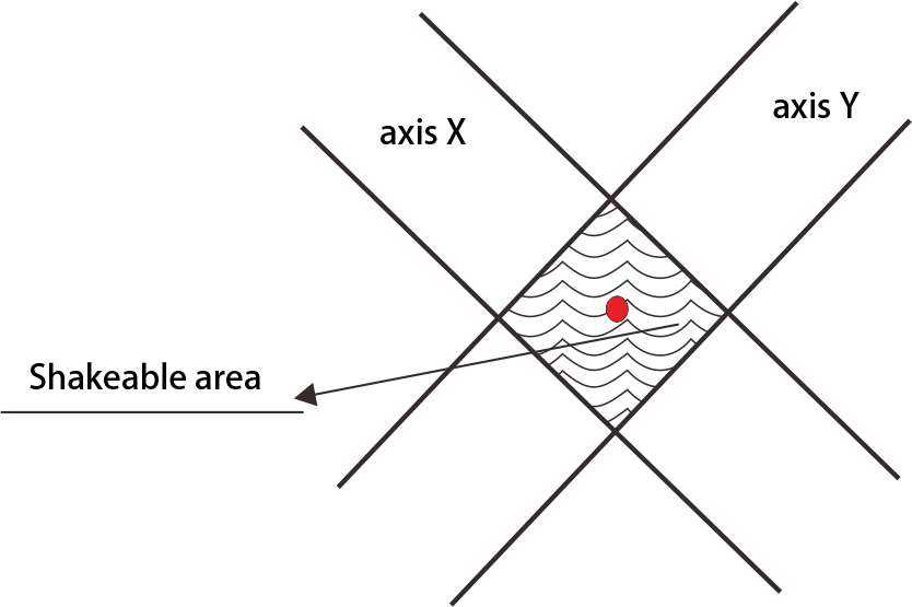
Figure 1: Probe Scanning Radiation Area
The detection principle is as follows
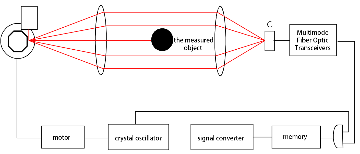
Figure 2: Working Principle
First, the mold oscillator generates self-excited high-frequency pulses, which are sent to the comparator and the stepping servo motor respectively. The stepping servo motor drives the octahedral prism to rotate at a high speed, and reflects the infrared laser emitted by the laser generator to the convex lens A. It becomes parallel light, and then collects on the photosensitive element C through the convex lens B in the infrared receiving probe. The photosensitive element C converts this signal into a corresponding electrical signal and sends it to the other end of the comparator to compare with the original signal.
When there is no object to be measured in the measuring probe, the pulse signal at both ends of the comparator will be the same. Therefore, there is no difference output: when there is an object to be measured in the measuring probe, the photosensitive element C will output no pulse signal during the period of scanning through the object to be measured. Therefore, there will be a difference input for a period of time at both ends of the comparator, which corresponds to the diameter of the measured object. By calculating the oscillation period of the pulse and the length of the time slice without pulse, the diameter of the measured object can be known.
The composition and functions of the system
The system consists of the following main parts (as shown in Figure 1)
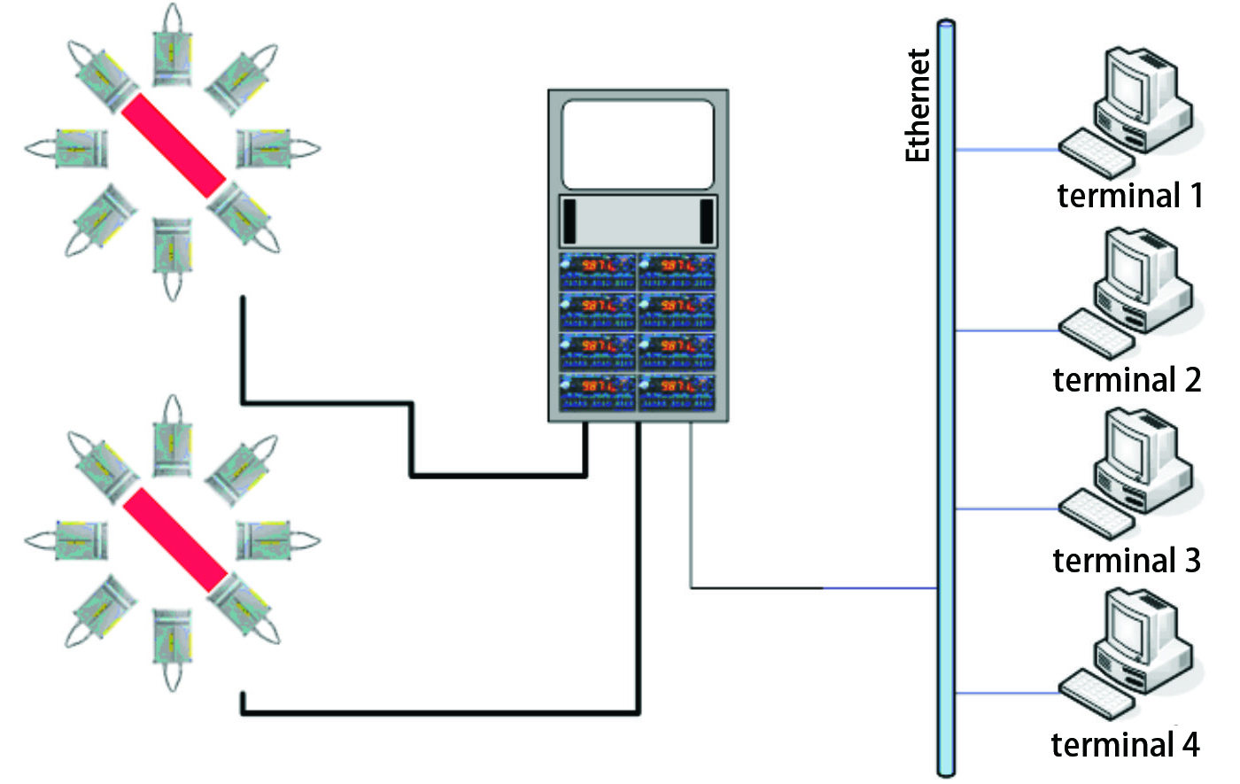
1. A measurement frame with four pairs of high-frequency laser scanning probes and non-contact infrared thermometers is installed
2. Four intelligent signal processors connected with four pairs of high frequency laser scanning probes
3. Cold air blowing system for cooling and cleaning the measuring frame
4. High-performance intelligent controller responsible for front-end data signal processing and network communication
5. Data processing and analysis system installed with industrial grade PC, monitor and printer
The technical indexes


